Simple bridge rectifier circuit Simple bridge rectifier circuit diagram Full wave rectifier circuit diagram (center tapped & bridge rectifier)
General circuit diagram of the Bridge rectifier (a) Full wave bridge
☑ draw the circuit diagram of bridge rectifier Rectifier diode capacitor Rectifier bridge
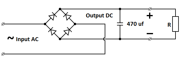
Bridge rectifier circuit diagram with filter
How to make bridge rectifier circuit diagramRectifier converter circuit Bridge rectifier diagram circuit working advantagesRectifier bridge diagram make schematic electronics project shown through go.
Simple bridge rectifier circuitBridge rectifier: functions, circuits and applications Rectifier capacitor operation diodes shocksCircuit bridge wave rectifiers input output rectifier voltage.

Rectifier diode rectifiers circuits
General circuit diagram of the bridge rectifier (a) full wave bridgeElectronics project: how to make a bridge rectifier Solved draw the circuit diagram for a bridgeCircuit diagram rectifier draw bridge wave solved.
Rectifier circuit diagramRectifier circuit diagram wave output waveform input Bridge rectifierRectifier circuit schematic.

Rectifier circuits
What should i consider when choosing the right diode…Bridge rectifier : circuit diagram, types, working & its applications Rectifier circuit bridge diagram wave working detailsRectifier bridge circuit working diagram theory operation diode controlled output power types its ic elprocus.
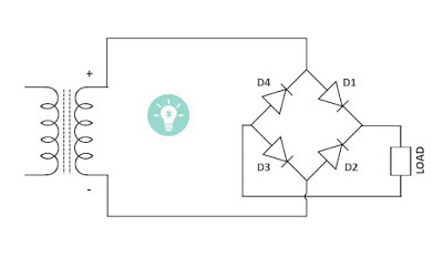
Gk, current affairs, tutorials & articles: rectifiers theory withRectifier bridge circuit circuits functions applications d3 d1 u2 conduction d4 d2 path stop current Simple ac to dc converter using bridge rectifierRectifier bridge circuit working diagram supply ac transformer theory its operation types.

Circuit rectifier bridge simple diagram
Full wave rectifier-bridge rectifier-circuit diagram with design & theoryRectifier circuit bridge simple diagram ac transformer voltage tapped providing using center Rectifier wave circuit filter without bridge diagram capacitor tapped diodes center type circuits four board below using circuitdigest electronic choose8: three-phase full-wave bridge rectifier circuit.
Bridge rectifier-working diagram advantagesSimple bridge rectifier circuit Bridge rectifier : circuit diagram, types, working & its applicationsRectifier circuit circuits alternating.
Bridge rectifier diagram make circuit
Full wave bridge rectifier circuit diagramBridge rectifier Rectifier schematic electronics.
.

ELECTRONICS PROJECT: HOW TO MAKE A BRIDGE RECTIFIER

Simple Bridge Rectifier Circuit

Full Wave Rectifier-Bridge Rectifier-Circuit Diagram with Design & Theory

Full Wave Rectifier Circuit Diagram (Center Tapped & Bridge Rectifier)

8: Three-phase full-wave bridge rectifier circuit | Download Scientific

Bridge Rectifier : Circuit Diagram, Types, Working & Its Applications

Full Wave Bridge Rectifier Circuit Diagram
