Decoders and logic gates Logic diagram Decoder nor gates using logic nand only line diagram draw
From Binary to Logic Part II: Logic Gates | by Lucas PenzeyMoog | Medium
2-to-4-decoder logic diagram 74154 4 to 16 decoder logic diagram Logic addition adder gates circuit binary quantum implement computers source ibms performing medium used max
2x4 function decoders implementing logic inputs decoder implement gates enable input digital bit stack
To the rails: may 2011Digital logic truth table generator Input schematic logic gate circuitlab breadboardCircuit decoder gate implementation combinational logic digital nand became instead active example ll low help show.
Digital logicQ. 4.23: draw the logic diagram of 2-to-4-line decoder using (a) nor Decoder circuit logic diagram digital decoders adv intro msi plds lecture clarkson university ppt powerpoint presentation lectSegment decoder schematic nand finding logisim schematics.

Logic diode circuits examples gates gate basic tutorial digital
Logic circuit gate gates decoders specific question next stackBinary decimal encoder deskripsi Decoder circuit ualberta webslides amaral webdocs courses cs ca ram logic diagram img027 gif constract help circuitsLogic gates.
Digital logic: digital logic,combinational circuitFrom binary to logic part ii: logic gates ☑ diode logic circuits examplesSegment display logic gates simple circuits digital may archive.

Logic circuit schematic generator gates diagrams boolean
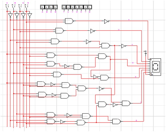
7 segment display logic diagram / 7 segment decoder implementationDigital logic circuit 12+ 4 to 2 priority encoder circuit diagramEncoder priority truth circuitdigest decoder.
Logic circuit digital schematic circuitlab created using input stackSegment logic display decoder gates circuit questions boolean please Decoder diagram logic nand gates stack use input outputs two g1 questions why will.


breadboard - Looking for the name of a 3-input logic gate - Electrical
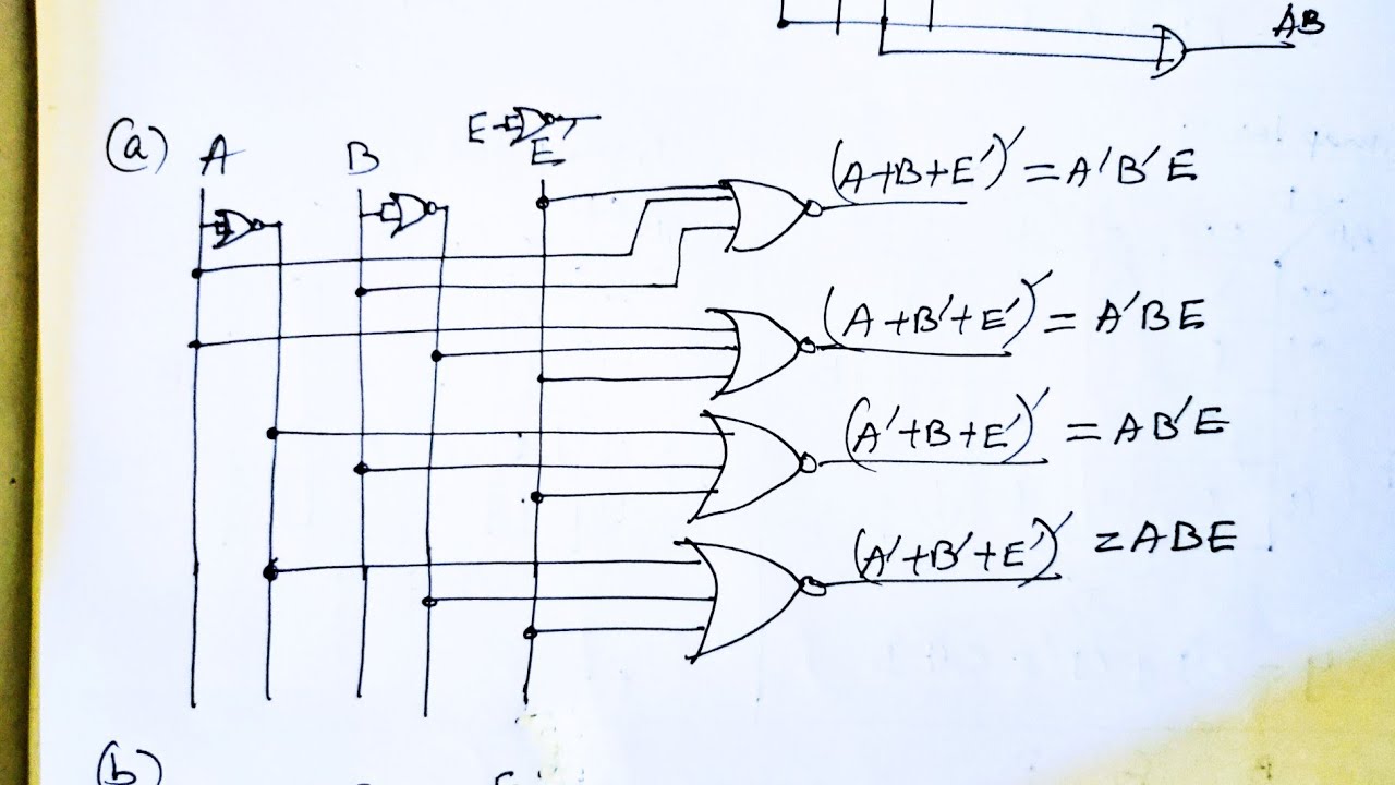
Q. 4.23: Draw the logic diagram of 2-to-4-line decoder using (a) NOR

74154 4 to 16 decoder logic diagram - Electrical Engineering Stack Exchange

7 Segment Display Logic Diagram / 7 Segment Decoder Implementation

Decoders and Logic Gates - Electrical Engineering Stack Exchange

digital logic truth table generator | Brokeasshome.com

Logic Diagram - PT Expertindo Training | Training dan Konsultan
To the Rails: May 2011

digital logic - Implementing a function with 4 inputs with 2x4 decoders
